Control Denitrification Using Online Sensors
Introduction
(Updated September 2021)
Nutrient removal from wastewater is an increasingly common requirement for water resource recovery facilities (WRRF) and nitrogen and phosphorus are the nutrients being targeted. Both are essential components of the machinery of living organisms. Nutrients dissolved in the water are assimilated by algae. In waters enriched with nutrients, algae growth and death is accelerated leading to hypoxia, a low oxygen condition unsuitable for fish and other higher life forms. In brackish waters, such as in Chesapeake Bay, Long Island Sound, and Puget Sound, nitrogen is the primary concern. The result is a substantial investment in improving the nitrogen removal capability of WRRFs that discharge to these watersheds.
Utilities are motivated to remove as much nitrogen as possible to comply with mass loading limits or even to earn credits that can be sold to other utilities. In groundwater, the concern is the toxicity of the drinking water from excess nitrogen. In situations where treated water is land-applied, Total inorganic nitrogen (TIN) is restricted to not more than 10 mg/L to protect against a serious condition called methemoglobinemia, which limits the ability of blood to carry oxygen. Infants and children are particularly susceptible to this potentially life-threatening condition.

Biological Denitrification
The most common method for removing nitrogen from used water is biological denitrification. Biological denitrification requires nitrification to generate nitrate, anoxic (low DO) conditions, and a carbon source. All three conditions can be achieved by placing an unaerated zone (anoxic zone) at the upstream end of an activated sludge tank and internally recycling nitrified mixed liquor from the downstream aerated (oxic) zone. This is based on a version of the activated sludge process called the modified Ludzack-Ettinger (MLE) configuration, shown in Figure 1.
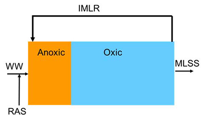
Figure 1 - Flow diagram for Modified Ludzack-Ettinger configuration
The anoxic zone is placed at the upstream end to make use of the carbon (COD) in the untreated water. If the water does not contain sufficient COD or if very low effluent nitrogen is required, an external carbon source may be required. Nitrate is the critical process parameter for controlling both the internal mixed liquor recirculation (IMLR) and external carbon dosing. Monitoring nitrate at the end of the anoxic and oxic zones provides the necessary information to achieve the required nitrogen removal at the lowest operating cost. The case study evaluation below illustrates how one customer used online monitoring of nitrate to optimize an MLE process.
MLE in Action
An industrial facility was facing a new discharge requirement to remove nitrogen from their wastewater prior to a land application. The first step was to modify the existing activated sludge treatment system to a MLE configuration. Modifications included converting an existing flow equalization basin into an anoxic tank and installing a new pump to recycle nitrate from an existing aerated basin to the anoxic tank.
Unlike municipal wastewater, industrial wastewaters are often imbalanced, meaning that it contains carbon and nitrogen in ratios not conducive to biological treatment. In this case, the untreated water contained high concentrations of nitrogen but relatively low concentrations of carbon. Therefore, a new chemical feed system was required to feed an external source of carbon (glycerin). Following modifications, 90 to 160 mg/L ammonia nitrogen in the untreated water was reduced to 15 to 25 mg/L Total Inorganic Nitrogen in the treated effluent. The removal rate improved greatly but was still not in compliance with the 10 mg/L limit. The next step involved deploying YSI VARiON sensors in the anoxic tank and oxic tank for monitoring ammonium and nitrogen continuously to identify the factors limiting performance.
Meeting Objectives
Online monitoring of the nitrate concentration at critical locations provides the information needed to achieve the three objectives for a denitrification control system:
- meet discharge limits for nitrogen;
- maximize use of wastewater COD;
- minimize the addition of external carbon.
In order to meet the objective (1), the nitrate concentration at the end of the oxic zone must be less than the discharge limit because substantial additional nitrate removal will not occur downstream. In order to meet objectives (1) and (2), the anoxic nitrate should also be at a low concentration. The operating cost to degrade COD under anoxic conditions is less than it is under oxic conditions which require the input of oxygen through energy-intensive aerators. In order to meet the objective (3), the carbon dosing system should be stopped when the effluent nitrate limit is met with internal recycling.
Objective (1) is not satisfied with the daily monitoring data shown in Figure 2.
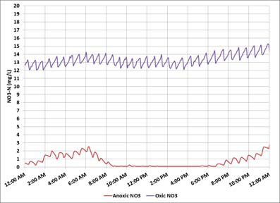
Figure 2 - Online nitrate monitoring - oxic nitrate high/ anoxic nitrate low
The oxic nitrate exceeds the limit. Objective (2) is also not satisfied because the anoxic zone nitrate is very low. Taken together, these conditions indicate that denitrification is nitrate-limited. Increasing the IMLR flow will bring more of the nitrified mixed liquor back to the anoxic zone increasing denitrification and maximizing the use of anoxic zone COD.
Objective (1) is also not satisfied on the day shown in Figure 3.
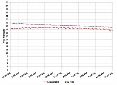
Figure 3 - Online nitrate monitoring - oxic nitrate high/ anoxic nitrate high
However, unlike in Figure 2, a high nitrate concentration in the oxic zone is accompanied by a high nitrate concentration in the anoxic zone. Objective (2) is being met, but denitrification is limited by the COD. Increasing the external carbon feed rate will stimulate the bacteria to consume additional nitrate.
This specific situation occurred over a weekend when production, and the carbon feed, was stopped while the IMLR remained active, transferring nitrate from the oxic zone to the anoxic zone. However, without carbon available, the denitrifying bacteria lacked the energy needed to transform the nitrate into nitrogen gas. There was no flow, so the nitrate concentration was not increased across the oxic zone due to nitrification of the waste, as would be the case in a municipal WRRF. The solution was to continue glycerin addition over weekends to provide the carbon needed for denitrification.
Objectives (1) and (2) are both met in the situation depicted in Figure 4.
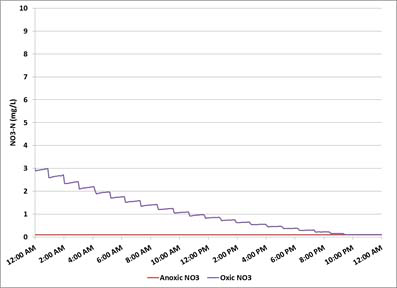
Figure 4 - Online nitrate monitoring - oxic nitrate low; anoxic nitrate low
The oxic nitrate concentration is within limits and the anoxic nitrate is practically zero. This would be a desirable situation in a WRRF with excess COD. However, in this case, the COD is from an external source which must be purchased at a great expense. In order to meet Objective (3), the carbon dosing system should be stopped when objective (1) is satisfied.
Results
Online monitoring with the IQ SensorNet allowed the facility to quickly identify limiting factors. Furthermore, operators were able to manually dial-in the optimum rates of IMLR and COD addition to meet treatment objectives and minimize operating expense. Automated control strategies based on feedback from online nitrate sensors are also possible.
A strategy proposed in the IWA publication Scientific and Technical Report No. 15, Instrumentation, “Control, and Automation in Wastewater Systems” comprises four feedback loops to achieve the three objectives stated above.
- Feedback loop A adjusts IMLR based on the oxic nitrate concentration to achieve the objective (1).
- Feedback loop B adjusts external carbon addition based on the anoxic nitrate concentration to achieve the objective (1) and objective (3).
- The use of wastewater COD is maximized (objective (2) using feedback loop C) when the oxic nitrate concentration is below a pre-defined setpoint (feedback loop A is not active). Feedback loops A and B or feedback loop C is active at any given time.
- A fourth feedback loop D is used to optimize the oxic nitrate setpoint concentration for feedback loop A. Regardless of the control strategy, online monitoring is essential for efficient denitrification.
Nitrate Monitoring Methods
Two types of immersible online nitrate sensors are available. Ion selective electrode (ISE) sensors were used in the case study described in this report. A nitrate ISE and ammonium ISE will fit on the same probe providing a versatile solution for also monitoring nitrification. ISE sensors require calibration and electrodes must be replaced when they no longer provide sufficient accuracy. Alternatively, nitrate can also be measured with an in situ spectrometric (optical) sensor based on the premise that it absorbs certain wavelengths of UV light directly without the need for reagents. Spectrometric sensors have a higher acquisition cost but lower ownership cost because the optics will last for many years. Also, optics are more stable such that a factory calibration is possible. User calibration is optional and may not need to be repeated at routine intervals. Optical measurement of COD, another critical parameter for denitrification, is also possible in situ and can be integrated together with nitrate measurement on the same probe.

Additional Blog Posts of Interest
Implementation of Solids Retention Time Control in Wastewater Treatment
How to Control Activated Sludge with Online Sensors
How Automated Orthophospohate Monitoring Cut Costs by 25 Percent