Control Activated Sludge with Online Sensors
Introduction
(Updated August 2021)
The goal for domestic wastewater treatment in the 21st century should be to have a minimal carbon footprint and to be 100% self-sustainable with regards to energy, carbon, and nutrients – while achieving a discharge or reuse quality that preserves the quality of receiving waters (Water Environment Research Foundation (WERF), 2009).
Sustainability with respect to energy requires both conservation and production. The obvious target for energy conservation is the activated sludge aeration system because it accounts for 25 to as much as 60 percent of total plant energy use (Water Environment Federation (WEF), 2009). Implementation of instrumentation, control, and automation (ICA) is critical to reducing energy consumption for aeration. Controlling dissolved oxygen (DO), for example, is reported to result in savings of 15 to 20% of electrical costs (Water Environment Federation (WEF), 2006).
The focus of this post is the use of online instrumentation for control of wastewater treatment aeration. Once considered the weakest link of ICA, the instrumentation is no longer a major barrier due to recent technological breakthroughs. The adoption of solid-state electronics and digital communication technology has dramatically increased the functionality of the measurement system. Modern online instruments are capable of measurements at a frequency, accuracy, and reliability suitable for process control at a reasonable cost. Furthermore, additional sensor options are available, including ion selective electrode (ISE) sensors for ammonium and nitrate and a new, more reliable optical DO measurement technology.
However, it is not just the measurement technology that has improved. Computing power is now practically free and no longer a limiting factor. It has enabled the development of inexpensive, commercial wastewater treatment simulators that capture the accumulated knowledge and understanding of the process and bring it right to operators’ and consultants’ desktops. It has enabled more widespread usage of distributed control systems, including programmable logic controllers (PLC).
New blower technologies have improved blower efficiency and increased turn-down capability allowing air supply to more closely match air demand. For example, single-stage centrifugal blowers equipped with inlet guide vanes and variable outlet vane diffusers makes it possible to operate the blower at its highest efficiency point, not only at the design condition but also within a greater range outside of the design condition (Environmental Protection Agency (USEPA), 2010). As a result, control strategies that are based on the needs of the process have emerged.
Manual Control
The simplest control method is manual adjustment of blowers and valves based on manual samplings and measurements using laboratory or handheld instruments to maintain desired setpoints. This is a form of the “Sneakernet” because it requires operators to physically transfer information by walking from process to instrument to control element. It was common in the early days following the passage of the Clean Water Act, especially for facilities required only to meet secondary treatment standards for total suspended solids (TSS) and biological oxygen demand (BOD).
Furthermore, treatment facilities were originally designed based on hefty safety factors applied to empirical standards for maximum loading conditions. In this case, the design priority was meeting discharge permit requirements under worst case conditions not providing flexibility to optimize operation for typical daily loads. Nonetheless, an attentive operator can observe the effect of manual adjustments on process performance and optimize the operating scheme for daily, weekly, and seasonal variations based on a formal or informal set of constraints.
The main drawback of this strategy is that the system is never optimized. System settings are optimum for only one loading condition (at most) depending on the availability of the operator and cannot closely reflect diurnal variations in demand. Furthermore, no adjustments can be made on days that the operator has more urgent tasks or on days the plant is not fully staffed, such as on weekends or holidays. The natural tendency is to adjust the system conservatively as a contingency to assure permit compliance while the process is not tended. The tradeoff is that treatment performance suffers and operating costs for energy and chemicals are higher than necessary.
Despite this disadvantage, manual is still the most common aeration control method used today. There are several reasons for this including the perceived unreliability of online instrumentation, the complexity of advanced control systems, and the cost to implement automatic control. One of the most important reasons is utilities’ unwillingness to adopt a higher level of automation. There is a resistance to change and a strong desire to keep things simple and not invest in training required to maintain online instrumentation. In other words, if it has worked for 40 years why change now? (Learn more, Wastewater Process Control - Which Strategy is Right for You?).
On the other hand, more stringent treatment requirements, the cost of energy, and the drive for sustainability are providing the incentive for more advanced control. Compliance with discharge permits now requires advanced treatment for removal of nitrogen and phosphorus requiring more stringent control of DO over a range of setpoints and a flexibility to adapt to wastewater loads that is beyond the capability of manual control. Furthermore, higher energy costs, and greatly diminished availability of grant and low-interest loan funds mean that treatment goals must be achieved at lower energy consumption with minimum construction. The logical solution is increased usage of ICA.
Open Loop Control (Sequencing)
The next level of control is open loop control, also known as sequencing, where control elements are turned on and off based on a timer and relays. The basic strategy does not utilize process measurements. Instead, predetermined cycle lengths are based on empirical design routines with additional modes for special situations like storm flows. The advantage is that the control system and the operation are simple. Blower operation will start and stop without operator attention. The drawback is that the system will operate inefficiently because it does not adapt to varying wastewater loads. A common application of this control strategy is a sequencing batch reactor (SBR) which cycles through stages of fill, react, and decant based on a timer. Figure 1 shows the operating cycle and response measurements in a typical SBR for one day.
The inefficiency of the system is demonstrated by observing the trend in ammonium concentration (the red line) which indicates the extent of nitrification, and the DO concentration. The cycles are conservatively designed to ensure sufficient treatment. The ammonium concentration is an indicator of the extent of treatment because nitrification is the rate-limiting step. DO spikes each cycle indicating that nitrification completes before the end of the cycle. When wastewater loads are high, the DO spike occurs towards the end of the aerated cycle. However, as wastewater loads decrease, the DO spike occurs earlier in the cycle. By the last cycle DO spikes immediately and the high concentration is carried through the end of the aerated period due to reduced oxygen demand. Maintaining elevated DO after nitrification is completed wastes energy.
Turning off blowers after the ammonia concentration reaches a target level would save energy and increase the capacity for denitrification (nitrate concentration in green). Additionally, adjusting cycle time to match treatment requirements could increase treatment capacity allowing the utility to defer capital expenditures for the construction of additional tanks and other infrastructure.
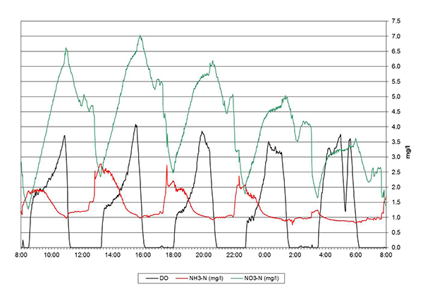
Figure 1: SBR Operating Cycles for a One-Day Period
Open loop control is simple and inexpensive to implement but will not be ideal. It is most suited to slow processes where disturbances are small and predictable, for example a package plant serving an institution such as a school or a limited number of households without substantial inflow and infiltration or industrial sources.
Closed Loop Control
Most wastewater treatment plants cannot be optimized using open loop control because wastewater characteristics vary quickly and sometimes unpredictably. Treatment must be provided for whatever comes down the pipe whenever it arrives. For this situation, closed loop control is required in which the process response is measured by online instrumentation and implemented in SCADA using PLCs and motorized variable actuators. This is also called feedback control as depicted in Figure 2. Changing wastewater loads result in a disturbance to the process which causes a response. The measurement is reported to a controller which reacts to eliminate the difference between the measurement and the desired setpoint, the error, by manipulating the control variable for an actuator on a valve or blower. Therefore, feedback control for aeration requires sensors to measure response variables, blower air flow control, basin air flow control, and a process control system.
Feedback control of aeration based on measurement of DO has been practiced for many years. However, calibration and routine maintenance required for traditional polarographic sensors were time-consuming and costly and limited more widespread adoption into aeration control strategies. The introduction of optical DO measurement technology, based on luminescence, is a significant innovation. Optical DO sensors are extraordinarily stable and do not require calibration for the lifetime of the sensing element which is typically 1 to 2 years. Furthermore, there are no membranes to replace, electrodes to clean, or electrolyte solution to replace as with polarographic sensors.
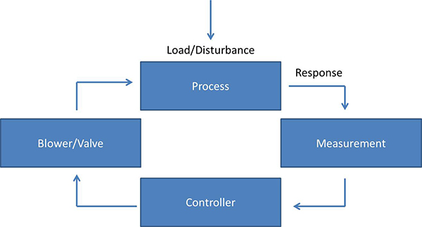
Figure 2: Feedback Principle; Source - Gustaf Olsson, Lund University, Sweden
The drawback to using DO as a response variable is that it does not provide information about the extent of reactions, e.g. nitrification or denitrification. The following examples show how measurements of complementary response variables in feedback control strategies can increase performance and efficiency.
- ORP: ORP provides an indication of the anoxic or anaerobic state of a reactor where DO concentrations are low or below detection limits as is required for biological removal of nitrate and phosphorus. For example, a slightly positive or negative ORP (-50 mV to +50 mV) indicates anoxic conditions for denitrification whereas a very negative ORP (<-100 mV) indicates anaerobic conditions suitable for phosphorus release. It is commonly used to determine the length of “off” stages in an on/off aeration control strategy for cyclic activated sludge or SBR systems.
- Ammonium: The development of stable ammonium ISEs is a significant innovation. ISE sensors provide a direct, instantaneous measurement without the need for the sample preparation systems or reagents that are required for automated wet chemistry systems, also known as cabinet analyzers. Furthermore , t h e acquisition cost is approximately one third and the annual costs of operation are one-half that of cabinet-style analyzers. Ammonium ISE sensors allow operators to directly monitor the status of nitrification. Monitoring of nitrification is critical to energy conservation because the nitrification rate increases in proportion to the DO concentration up to approximately 1.5 mg/L. Above 2.0 mg/L, only marginal increases in the rate of nitrification are observed. Therefore, lower energy usage is achieved by maintaining a DO not higher than 2.0 mg/L when ammonia concentrations are high and reducing air supply to the minimum required for mixing after nitrification is complete.
- Nitrate/Nitrite: Nitrate ISE technology is not new but there have been important innovations. Probes are now available with nitrate, ammonium, and compensation electrodes greatly increasing the accuracy and functionality of the instrument. Nitrate is used in place of ORP as a direct measure of denitrification to control aeration in cyclic activated sludge and SBRs. It is most useful for controlling sludge recirculation (RAS or IMLR) in BNR activated sludge.
- COD: Measurement of COD is one of the most exciting developments in sensor technology, made possible by digital technology and ever-smaller electronics. A COD sensor is basically a submersible spectrophotometer. Measurement of COD without wet chemistry is possible because most organic molecules absorb ultraviolet (UV) radiation. The raw measurements from a wide range of wavelengths over the UV and visible range can be used to calculate COD and compensate for interferences using statistical techniques. Measurement of influent COD combined with ammonium, allows for an accurate online oxygen demand prediction for feed forward control.
On-Off Control
The simplest form of feedback control is on-off control. Like sequencing, it is relay-based. However, instead of operation based on a timer, aeration is started and stopped in response to online measurements of response variables. The control variable assumes a maximum (blower on/valve open) when the error is greater than zero and minimum (blower off/valve closed) when the error is less than zero. On-off control is inexpensive and can be easily retrofitted into existing facilities. Only minor control modifications are required, particularly for facilities where separate batteries of blowers are used for each aeration basin in place of a common blower system such that basin air flow control and blower air flow control are the same.
The major capital expenses are for mixers to uncouple mixing and aeration. The main drawbacks to on-off control are smooth control is not possible, slow system response, and excessive actuator wear. Figure 3 illustrates each of these drawbacks. At the beginning of the aeration stage, the oxygen demand of the bacteria is greater than the oxygen supply at the max rate, resulting in a slow rise of DO up to the 2.0 mg/L setpoint. Even when supply does catch up to demand, the rate is such that the on-off cycles are very short and the DO never settles at the setpoint. Towards the end of the aeration stage, the “off” airflow intervals lengthen as a result of decreasing oxygen demand. The “on” airflow aeration stages decrease because even short pulses of air cause a persistent overshoot of the DO setpoint.
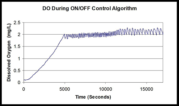
Figure 3: On-Off Control Dissolved Oxygen Response; Source - Meck, D., R. Odum, N. Wobbrock, Cornell University
A dead zone or hysteresis is typically inserted into an on-off controller to limit wear on the actuators due to starting and stopping. Dead zone defines a range above and below the setpoint where a control action is not taken. The system is “dead” in a defined range above and below the setpoint. Hysteresis is similar except that a range above the setpoint is defined where a control action is not taken. Hysteresis may also be used with a delay timer.
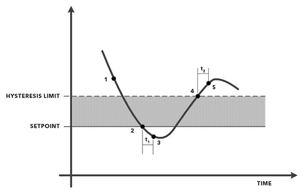
Figure 4: On-Off Control with Hysteresis
The principle is illustrated in Figure 4. The actions at each numbered point are as follows:
- Relay open, blower off;
- DO falls below the setpoint starting switching delay timer, t1;
- The switching delay expires, the relay closes, the blower turns on;
- DO rises above the setpoint hysteresis limit, starting switching delay timer, t2.
- Switching delay expires, relay opens, blower shuts off.
On-off control is most suitable for completely mixed reactors with long hydraulic and solids retention times. On-off control based on DO setpoints can be combined with analysis of bending points in curves from online instrumentation for a more advanced control strategy. An inflection point in the pH and ORP curves shown in Figure 5 indicates when ammonia is depleted and the air can be shut off. Similarly, the strategy can also be extended for denitrification using ORP or nitrate. The so-called “nitrate knee” indicates when nitrate is depleted and air should be turned on.
PID Control
Greater aeration efficiency requires a proportional integral-derivative or PID controller to more closely match the air supply to the oxygen demand. The PID controller has been around for decades and is far and away the most common controller used in the process industries. It gets its name from the three actions it applies: Proportional action, Integral action, and Derivative action. The proportional term provides a control signal in proportion to the magnitude of the error. Proportional control of DO is unstable if the gain is set too high. DO is driven towards the set-point at a high rate initially, causing overshoot.
Overshoot occurs again on the return and becomes less and less as the system oscillates above and below the setpoint and hunts for a stable condition. If another disturbance occurs before the system stabilizes the hunting continues. The integral term provides a signal proportional to the duration of the error. With a PI controller the gain can be set lower and the I term ensures the setpoint is reached. Derivative action is proportional to the rate of change of the error. In theory, this could be used at facilities where sudden and substantial changes in load occur on account of storm events or industrial discharges. In practice, derivative action is rarely utilized.
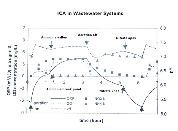
Figure 5: Bending Point Diagram. Reproduced G. Olsson, M. Neilsen, Z. Yuan, A. Lynggaard-Jensen, J-P Steyer (2005), Science & Technical Report No. 15, Instrumentation, Control, and Automation in Wastewater Systems, with permission from the copyright holders, IWA Publishing.
Direct Control Based on Dissolved Oxygen
The simplest method for PID feedback control of DO is the direct adjustment of the air supply rate based on the DO measurement. However, this strategy has limited applicability due to the nonlinear relationship between air flow and DO. Therefore, direct control is most suitable for use with mechanical aeration systems or diffused aeration systems in which each aeration basin has a dedicated air supply.
Cascade Control Based on Dissolved Oxygen
The standard configuration for a DO control system utilizing PID control is a cascaded control system shown in Figure 6. The DO controller, typically a PI controller, calculates the airflow required based on the difference between the input DO setpoint and DO sensor measurement. The output from the DO controller is the setpoint for the airflow controller (the slave) which compares the airflow setpoint with the actual airflow and adjusts the basin or zone air flow valve accordingly. A P controller is recommended for air flow, allowing the DO controller to correct any errors in the airflow. A PI – PI controller will be less stable because the two controllers will work against one another.
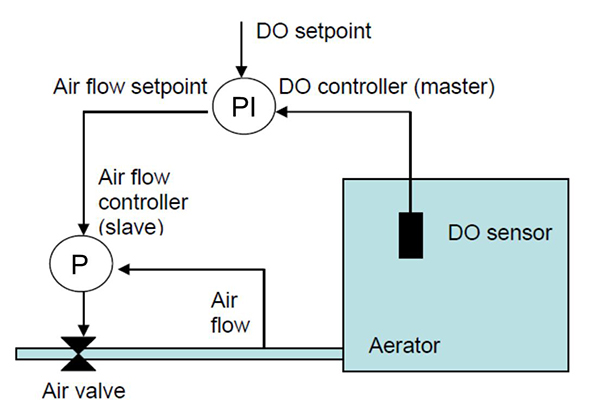
Figure 6: Dissolved Oxygen Cascade Control Diagram; Source - Gustaf Olsson, Lund University, Sweden
Of course, pressure in the main air header will increase or decrease in response to changing air flow demand. The non-linear relationship between air flow and DO concentration and the lag time to reach equilibrium in response to changing air flow results in setpoint overshoot causing repeated adjustment of control valves and actuators. Therefore, a second control loop is required to adjust the blower air flow in response to the pressure in the main air header. The most open valve (MOV) control strategy attempts to optimize blower and valve adjustments by ensuring that the valve serving the zone or basin with the highest air demand is full open.
Direct Control/Ammonium
The ideal response variable for facilities required to remove ammonia-nitrogen is, of course, ammonia. Nitrification is the rate-limiting step which means that complete nitrification assures that BOD is also removed. Two methods of feedback control with online ammonium sensors are practiced. The direct method uses the ammonium sensor in place of the DO sensor in a cascade arrangement. The problem with this strategy is that DO responds much faster than the ammonium concentration. Consequently, DO fluctuates as the ammonium controller adjusts the airflow setpoint. Typically, a DO sensor is also installed as a constraint to limit air flow above a defined DO concentration. This prevents overaeration but is a troublesome tuning problem.
Cascade Control/Ammonium
A more desirable strategy is to add the ammonium controller on top of the DO controller in a cascade arrangement. In the cascade strategy, the ammonium controller, typically a PI controller, sets the DO setpoint based on the ammonium concentration and the DO controller calculates the airflow requirement as in the standard configuration. For example, a DO of 2.0 mg/L when ammonium is greater than a certain concentration to speed up the reaction and a lower DO to reduce aeration energy usage when ammonium is nearly depleted. A critical aspect of this strategy is the selection of sampling times. The ammonium control loop has to be much slower than the DO control loop for the control system to work properly.
Barriers to Feedback Control
Feedback control is not yet widely utilized for wastewater aeration control in North America for various reasons including an understanding of the process, cost, complexity, and incentive. What isn’t understood can’t be controlled. Fortunately, the understanding of the dynamics of nutrient removal has improved substantially in recent years and the accumulated knowledge is built-in to easily accessible wastewater simulators. With understanding, the aeration system, including the controls, can be designed appropriately.
Additional costs are required to purchase sensors and control equipment, obviously. However, the greatest cost is the cost of upgrading the air supply and distribution system. A control system can’t function without suitable control elements. Basin air valves need to be motorized, positive displacement blowers require VFDs, and centrifugal blowers require inlet throttling, at least. Blower replacement may be needed to achieve the highest efficiency. The workhorse for decades has been the multi-stage centrifugal blower. These machines have limited turndown capability and their efficiency declines significantly with inlet vane throttling.
Furthermore, blowers remain in service for decades. Back when they were originally installed coarse bubble diffusers were the standard. Fine bubble diffusers which provide much higher oxygen transfer efficiency are now the standard but require higher discharge pressures. Consequently, the blowers operate further out on their system curve than the original design limiting the available operating range. Reconfiguration of the air distribution system in the aeration tanks may also be required to supply the required aeration density.
Feedback control requires instruments, controllers, and actuators. A malfunction of any one of the three components will result in an inadequate response. Proper maintenance of the instruments is crucial. Therefore, training is very important to achieve operator buy-in and commitment. In many cases, online instrumentation is simple to maintain. The most important task is verification of the measurements at regular intervals or when readings do not match expectations. Handheld instruments or sampling and analysis in the lab using a colorimeter provide quick and inexpensive methods for this purpose. Even without a malfunction, a control system will perform poorly if not properly tuned. The perception is that feedback control is complex and requires hiring consultants, integrators, and electricians. However, there are systems today that do not require advanced engineering. In addition, autotuners are available to simplify the tuning procedure.
It is also significant that utilities have not had sufficient incentive to implement automation. Rising energy costs and resistance to increasing operating budgets will overcome this barrier. In Europe, for example, where energy costs are higher, DO control is much more common.
Feed Forward Control
Feed forward control involves measurement of the load (disturbance) and adjustment of blowers and valves based on the predicted response. Calculation of the load requires measurement of wastewater flow and ammonium, if nitrification is required, or COD if nitrification is not required. A reasonably accurate model is also required to calculate the predicted oxygen demand and aeration rate. Feed forward control is superior to feedback control for responding to peak loading situations and, as a result, has the potential to produce higher quality effluent more consistently. The feed forward aeration control system used at Wheaton, IL Sanitary District consists of a PLC that calculates the required air flow based on a number of factors, including upstream ammonium concentration from online sensors, and adjusts air flow accordingly.
When the measured ammonium is below a threshold concentration, the control system maintains a minimum airflow for mixing. Figure 7 demonstrates the capability of feed forward control to keep up with oxygen demand, even during peak periods. The system used an average of 3,666 standard cubic feet per minute (scfm) of air (1.14 scfm/lb BOD treated). Energy savings compared with no control was calculated to be 11% compared with DO feedback control (Poole, 2012). However, feed forward control without feedback is usually not recommended. Feedback control will compensate for inaccuracy caused by the feed forward control. Feedback loops are also typically incorporated to account for errors in the predicted response increasing the complexity and cost of implementation.
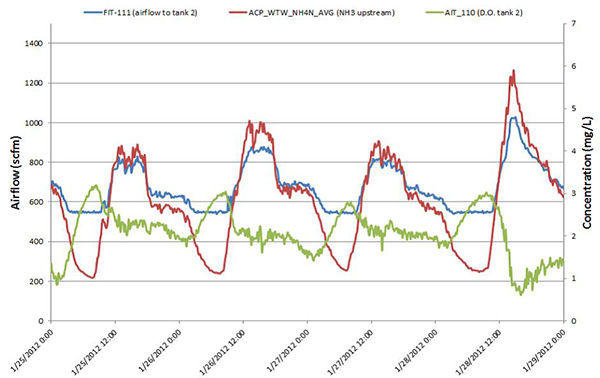
Figure 7: Feed Forward Control; Source - Poole, et al (2012)
Aeration Control Cost-Benefit
It has been estimated that DO control systems reduce energy consumption compared to manual control by 50 to 100 kWh per million gallons treated (Burton, 1998). Implementation of DO control at the Sheboygan, Wisconsin WWTP reduced energy consumption by an estimated 459,000 kWh, approximately 105 kWh per million gallons treated (Environmental Protection Agency (USEPA), 2010). The estimated cost savings was $65,000 annually resulting in a simple payback of fewer than two years. Interestingly, the DO control component was not part of the original project which included new blowers. It was only added in after operators were unable to control wide fluctuations in DO. The new control system more than do bled the energy savings for a much smaller investment.
The J.D. Phillips Water Reclamation Facility in Colorado Springs, CO implemented ammonium-based aeration control to minimize aeration energy for nitrification. A brief trial period demonstrated that an estimated annual energy savings of $50,000 could be achieved by simply reducing the DO setpoint during daily low flow periods (Brischke, 2010).
The above examples aside, evaluation of cost-benefit for aeration control projects is not straightforward. Energy savings as a result of a control project are not typically reported if the accounting is even performed. One important reason is that assigning costs and benefits is challenging. Wastewater treatment plants are complex and so are the improvement projects that include control components. Multiple improvements are usually bundled together, for example switching to another form of aeration or replacing diffusers or blowers. It is no easier to assign benefits. Utilities do not keep track of expenses at the process or system level. For example, electric submetering of equipment is not typical. Nevertheless, it makes sense that aeration control saves energy and reduces operating costs. The strong and growing interest in aeration control projects is evidence that utilities see the value in aeration control. Simple examples shown in the sidebar demonstrate energy and cost savings potential.
Summary
Instrumentation, control and automation (ICA) is becoming a basic requirement because the “Sneakernet” is simply not practical for efficiently meeting increasingly stringent treatment requirements. For example, strict control of DO is required in order to create the conditions necessary to achieve biological removal of nitrogen and phosphorus. Fortunately, technological advances have enabled the design and operation of the aeration system to match the process oxygen demand, improving process performance and reducing energy consumption. Modern online instruments are capable of measurements at a frequency, accuracy, and reliability suitable for feedback or even feed forward control of aeration. The best strategy for a facility must take into consideration several factors including the characteristics of the wastewater, discharge limits, and the treatment process. However, cascade control of aeration based on measurement of DO and ammonium and implemented through a PID controller offers the greatest potential for energy efficiency and process performance. Implementation of PID control at a wastewater facility will require outside technical expertise and investment in instrumentation and control systems, of course. However, the greatest barrier is typically the cost of replacing blowers, valves, and air distribution systems to match the capability of the control system.
References
Environmental Protection Agency (USEPA). (2010). Evaluation of Energy Conservatioin Measures for Wastewater Treatment Facilities. Washington, D.C.: USEPA.
Poole, A. N., et al (2012). Comparison of Ammonia and DO Aeration Control Strategies to Optimize Energy and Performance at Low Capital Cost: A Case Study. WEFTEC. New Orleans, LA.
Water Environment Federation (WEF). (2006). Manual of Practice No. 21 (MOP-21) Automation of Wastewater Treatment Plants. New York: McGraw-Hill.
Water Environment Federation (WEF). (2009). Manual of Practice (MOP) No. 32: Energy Conservation in Water and Wastewater Facilities. Prepared by the Energy Conservation in Water and Wastewater. New York: McGraw-Hill.
Water Environment Research Foundation (WERF). (2009). Technology Roadmap for Sustainable Wastewater. Alexandria, VA: Water Environment Reserach Foundation.
I am most grateful to Dr. Gustaf Olsson and Dr. Sam Jeyanayagam for their encouragement and helpful comments.

Additional Blog Posts of Interest
Activated Sludge | Three Steps to Improve Your Process Efficiency
Water Reclamation Facility Meets Discharge Limits for Total Inorganic Nitrogen
How Automated Orthophosphate Monitoring Cut Costs by 25 Percent
Chemical Oxygen Demand in Influent Wastewater Monitoring